We first did this project a few years ago. The bulbs used back then are no longer available. Here’s a refreshed guide for a new model bulb with a more powerful processor and much better color and tunable-white (RTBCCT).
Smart bulbs are great. Change colors, change brightness, turn on/off from phone. But then it happens. Someone turns the lamp off and the smart bulb is unavailable because it’s been cut off from power. Dang.
I fundamentally believe that automation/smart-home stuff shouldn’t impact usability — if there’s a switch, it should work as it is intended to. This write-up will detail how to put a smart-bulb in a lamp and have it be fully available for automations, voice-assistants, and phone/computer control…..while still providing a standard rotary switch at the lamp that works as intended and does not prevent home automation software from interacting with the light as well. The switch can turn the bulb on/off at any time, and home automation software (Home Assistant, for example) can fully control the bulb as well.
This hack extends two wires from inside the bulb for switch attachment. The voltage on these two
wires is 0vdc and if the project is executed correctly, no dangerous voltages are present
outside the bulb.
We will walk through flashing the bulb to Tasmota software and adding an external switch to toggle the bulb on/off. The bulbs we are using are made by Vont. They’re readily available on Amazon, they have an ESP32 processor/Wifi chip in them, and they’re cheap.

First — take off the diffuser. Grab, hold, twist and pull, and it should come off. It’s glued on but should come loose without too much effort. Once it’s off, use a tool to scrape away the silicon that is holding the LED board onto the body of the bulb. A knife or screwdriver will work, I used a spudger.
 Once the glue is scraped away, insert a spudger or thin pry tool into the gap between the metal LED circuit board and the metal bulb housing edge and gently pry up slightly. Do this on both sides, but only pry up 1/4 inch or so.
 Once you have the LED board elevated, slide the spudger or pry tool around to the edge nearest the pin connectors. Put your finger on the Wifi chip in the middle to hold it down inside the bulb, and gently pry up. The pins on the internal circuit board will slide out and disconnect from the LED board itself.


 Here we can see the solder points we will use to flash new firmware to the bulb controller, and the solder points we will connect our rotary switch to as well:

We will solder wires to the TX, RX, +3.3v, GND, and IO9 solder points
The hardware kit has several wires in it:
- 5x wires bare on one end, female DuPont on other end
- 2x wires bare on both ends
- 2x “clip style” wire connectors
- 1 3-pin header with the pins all soldered together.
- 1x wire with DuPont connectors on each end (GND/ground pin jumper)NOTE: When you are done with your project, please put the clip connectors, the 3-pin header, and the other pieces back into the bag and return it to Matt/Jeff or one of the HHV volunteers. We try to re-use materials if possible to keep all costs to a minimum.


2x bare wires on both ends: one wire will have one end soldered to the GND. The other wire will have one end soldered to the RX solder point.
3x wires with female DuPont connectors will have their bare/stripped end soldered to TX, 3.3v, and IO9 solder point.
Solder the IO9 wire first, followed by GND, RX, TX, and 3.3v (in that order)
NOTE: The solder point labeled GND that is located immediately next to the IO9 solder opint is not used. Use the GND solder point that is in the row witht RX/TX/3.3v

Wires from GND and RX will have their remaining bare stripped ends connected to a “clip style” wire connector. Each bare end will connect to a separate clip connector. Insert the wire into the clip connector such that the stripped part of the wire overlaps the orange lever when in the open position, then push the close lever down. See images for reference:


For programming the bulb, we will use a USB programmer with a USB connector on one end of a
small circuit board, and a 5, 6 or 10 pin header on the other end. The programmer is a tool for use
in the HHV workshop and is not included in the smart bulb kit. If you wish to get your own
programmer, they are inexpensive and available here:
https://amzn.to/3mpY1cy
IO9 solder point from the bulb needs to be connected to GROUND to enable bootloader mode. Bootloader mode allows us to re-flash the internal memory in the bulb with our own code. We must also connect the GND/ground solder point to GND/ground on our programmer, we will use the 3-pin header block to connect everything. The 3 pins of the block have been soldered together to have connectivity across all 3 pins. We will use 1 pin to connect to the IO9 point, another pin to connect to GND/ground on the bulb, and the 3rd pin will connect to the GND/ground pin on the programmer itself.

Bulb TX –> Programmer RX
Bulb RX –> Programmer TX
Bulb 3.3v –> Programmer 3.3v
NOTE NOTE NOTE: Make sure to connect the Bulb 3.3v wire to the 3.3v pin on the programmer. If the 5v pin on the programmer is used, it will destroy the bulb.
Bulb GND/Bulb IO9 –> Programmer Ground. A block of 3 header pins will be used to connect both pins (IO9 and GND) from the bulb to the single ground pin (GND) on the programmer. See image for guidance:

When IO9 is connected to ground, the ESP32 chip boots to bootloader/programming mode and we can flash different firmware to the chip. We will flash Tasmota firmware (https://tasmota.github.io/docs/). After being flashed, the bulb will work with no cloud connectivity, and we can control it via MQTT/API/web interface as well as integrate it into any standards-based home automation software package. We also gain full control of the input/output pins and can add functionality.
To flash the bulb:
With the wires all properly connected to the programmer, and the programmer plugged into the laptop.

Launch the esp_flasher program. It can be found in the Kernelcon folder on the desktop/home screen.

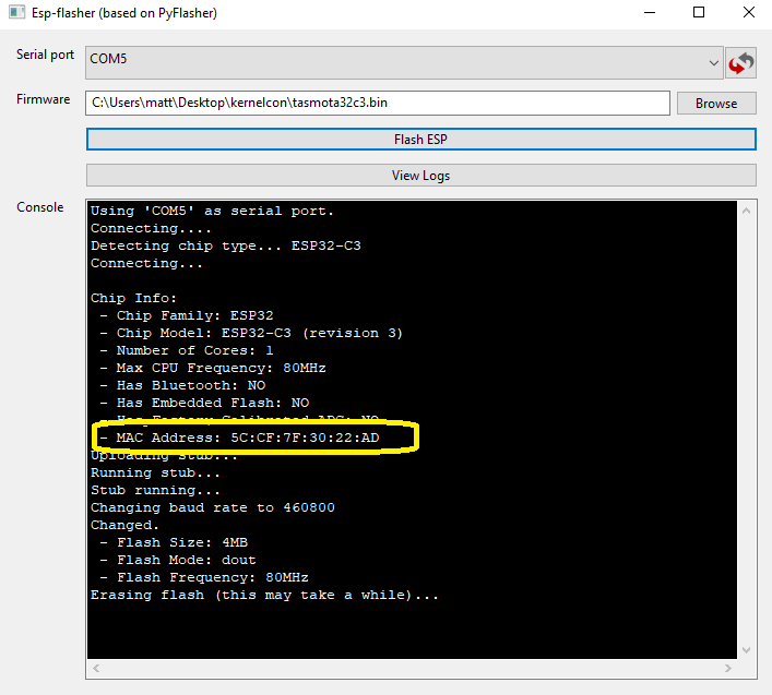
From the drop down menu, select the available COM port. ESP_Flasher will automatically find and identify ports with chip programmers plugged in. The example below shows COM5 – yours may be a different COM port number (likely COM4). Whatever COM port is shown, please take note as we will need this later.

Click the “browse” button and choose the tasmota32c3.bin file – this is the new firmware file we will load to the bulb’s internal chip.

Click “Flash ESP” and the process will flash. See screenshots for guidance. The flash process takes several seconds to erase. If the flasher seems to be frozen, just wait a minute for it to progress.
Take note of the MAC address that is shown during flashing. If it scrolls by too quickly for you to record, you can scroll up through the log file when the flashing process finishes. It is critical to record this MAC address for later use:
When finished, you will see the following screen.

This means we have successfully flashed this light bulb and we can now take full control over how it operates.
Close the ESP Flasher utility.
We will now use a soldering iron to disconnect several wires from the bulb solder points
Heat up and disconnect the following wires:
IO9
3v3
TX
You will be left with short wires still connected to the RX and GND solder points. See picture for reference:

At this point, we are ready to attach our rotary switch. It doesn’t matter which wire connects to which leg/wire of the switch — All the switch does is connect/disconnect a solder point to ground.
Feed the wires from the bulb through the center of the LED board. Push the LED board back into position. Take care to line up the pins on the main board with the pin holes on the LED board:


Use the soldering iron to make a small “notch” in the edge of the bulb diffuser. The wires will pass through this notch. Make sure the notch is big enough for the wires to fit through without pinching or smashing. It needs to be larger than you think. Smooth the edges with the soldering iron or the diffuser won’t properly snap back into the bulb base. If needed, the diffuser can be glued on with a small bit of hot glue.


Connect /solder rotary switch wires to the two wires coming out from the bulb. It does not matter which wire from the bulb goes to which wire on the rotary switch. Wire holders are available, or ask a HHV staff to help hold wires if you need assistance.

Use a piece of electrical tape to cover the solder joints between the bulb wires and the switch wires.


Hardware modification is complete. Now we will finish software configuration.
Use the provided bulb/outlet adapter to plug your bulb into a power outlet.
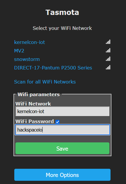
Recall from the flashing step above, the MAC address that was recorded. From your laptop, open the available wireless networks list. Look for and connect to the tasmota-xxxx-xxxx network name where the -xxxx-xxxx contains the characters from your smart bulb’s MAC address. In the screenshots provided, the flashing log showed MAC address of 5C:CF:7F:30:22:AD, and we see a wireless network containing the 6 characters at the end of the mac address (3022AD). This is how you verify which SSID belongs to your bulb.

Upon connecting, you should be redirected to a Wifi configuration screen:

Select the “kernelcon-iot” network
Type the password hackspaceio
Click “Save”
 If a save password prompt pops up, escape/cancel it quickly
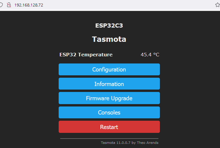
The bulb will start to connect to the network — once it connects, it will display the IP address of the bulb. Take note of the IP address. It will be in the format of 192.168.128.xx

Re-connect your laptop to the “kernelcon-iot” network if it does not automatically reconnect itself.
In a Firefox/browser window – type the IP address that you noted just a moment ago when the bulb connected to the wireless network. It should be 192.168.128.xxx. Web interface will look like this:
We will apply a template to the device. A template is a configuration string that maps the inputs and outputs of the bulb’s hardware together. Since we re-wrote the firmware, we have to tell the bulb microcontroller how to connect to the LED board and the rotary switch.
Click “Consoles”

Click “Console” again

In the box where it says “Enter command”, paste the following text:
backlog template {"NAME":"Vont ESP32-C3 A19 RGBCT Rotary","GPIO":[0,0,0,452,419,418,416,417,0,0,0,0,0,0,0,0,0,0,0,0,160,0],"FLAG":0,"BASE":1,"CMND":"so92 1"}; module 0; so92 1; so59 1; wificonfig 2;
After pasting the text string in the “Enter command” box, press enter.

The bulb will reboot.
Click the “Consoles” button
Click the “Main Menu” button
You should see a colorful screen looking like this:

You can adjust the color, richness of color, and the white balance (blue/cool-white to yellow/warm-light) and the bulb will respond.
Turning the rotary switch will toggle the bulb on/off, and it remains in sync with the web interface. The bulb itself always has power.
When finished with the lab activity – reset the Wifi settings of the bulb. The bulb is configured to look for the “Kernelcon IOT” network, which will not exist at your home. Upon failure to connect, the bulb should revert to broadcasting an SSID and allowing you to configure just as we did in the lab, but it is best to make sure the bulb will be in access point mode by resetting the wifi configuration before leaving the HHV at Kernelcon:
From the main web interface:
Consoles –> Console
In the bottom command window area type:
reset 3
Press “Enter” key. This will reset Wifi to default state, and bulb will boot to access point mode.
Further Information:
I use a zip-tie to attach the rotary switch alongside/over top the default lamp switch. When a person reaches up to feel for the switch, they find the modified switch to the bulb and turn it without even thinking.

You can add the bulb via MQTT to your home automation system (Hubitat, Smart-Things, Home-Assistant, Node-Red, anything!) for 100% local control. Alternatively, you can enable Phillips Hue emulation and Google Home/Alexa can discover the bulb and control it.
Enable HUE emulation:
- Configuration -> Configure Other
- Change Device Name and Friendly Name to reflect what the device is (Example: Livingroom Lamp)
- In the Emulation section, click “Hue Bridge”
- Save
- Perform device discovery on Google Home/Alexa/Smart Things.
- There is more information on Hue emulation here: https://tasmota.github.io/docs/Alexa/
If someone sits down at the couch and turns the bulb off using the rotary switch, you can still turn it on using your phone or voice commands.
If someone uses the rotary switch to turn the bulb off, the bulb can still turn itself on due to automation triggers or timer events. The power to the bulb is not cut off.
The bulb can also participate in Tasmota Device Groups. A smart wall switch or dimmer running Tasmota firmware can control the brightness, color, and on/off state of the bulb. If there are multiple lamps/bulbs in a room, the smart dimmer or wall switch can control all bulbs/lamps.
Device group information is here: https://tasmota.github.io/docs/Device-Groups/